


25MJ 1064NMレーザーターゲット指定子
STA-106425M中程度のレーザー光度計(以下、レーザー光度計と呼ばれる)は、レーザーを特定のターゲットに伝達し、レーザー飛行時間に従って距離情報を計算する精密光電製品です。 25MJ 1064NMレーザーターゲット指定子には、優れたパフォーマンスと単純な操作の特性があります。
モデル:JIO-106425M
お問い合わせを送信
製品説明
25mJ 1064nm Laser Target Designator TECHNICAL SPECIFICATIONS
| PERFORMANCE SPECIFICATIONS | |
| Laser wavelength | 1.064μm |
| Pulse average energy | ≥25mJ |
| Pulse capacity fluctuation | within a cycle, adjacent pulse fluctuation ≤8%(statistics after 2 seconds of light output) |
| Laser beam dispersion Angle | ≤0.5mrad |
| Laser optical axis stability | ≤0.05mrad |
| Pulse width | ≤20ns |
| Power-on preparation time | ≤3s |
| RANGING PERFORMANCE | |
| Ranging frequency | 1Hz, 5Hz, single time |
| Continuous ranging time | 5min(1Hz), 1min(5Hz) |
| 5Hz maximum continuous operating time | 2min |
| Minimum range | ≤100m |
| Typical ranging capacity | ≥2000m |
| Ranging accuracy | ±2m |
| Accurate measurement rate | ≥ 98% |
| Ranging logic: first and last target | first and last target |
| IRRADIATION PERFORMANCE | |
| Irradiation distance | ≥2km |
| Irradiation frequency | fundamental frequency 20Hz |
| Coding | in line with system requirements; With the ability to customize coding extension |
| Encoding mode | precise frequency code |
| Encoding accuracy | ≤±2.5μs |
| Irradiation mode | one irradiation time ≥20s, start irradiation again, interval ≤15s, can be continuously irradiated for 8 cycles |
| WEIGHT AND SIZE | |
| Weight | ≤450g |
| Size | ≤67.4mm×51mm×90mm |
| POWER SUPPLY VOLTAGE | |
| Voltage | 19.6V ~ 25.2V |
| POWER CONSUMPTION | |
| Standby power consumption | ≤4W |
| Average power consumption | ≤50W |
| Peak power consumption | ≤90W |
| ENVIRONMENTDL ADAPTABILITY | |
| Working temperature | -40℃ ~ 55℃ |
| Storage temperature | -55℃ ~ 70℃ |
CONTROL FUNCTION
2.1 With laser ranging function;
2.2 Provide target laser irradiation;
2.3 Be able to communicate with the host computer according to the requirements of the communication protocol.
The laser imager can realize the following functions through the serial communication interface:
2.3.1 Response laser ranging instruction, and can be stopped at any time according to the stop instruction;
2.3.2 Distance data and state information are output per pulse when ranging;
2.3.3 Ranging with distance gating function;
2.3.4 Start continuous ranging did not receive stop instruction 5min(1Hz)/1min(5Hz) after the automatic stop ranging;
2.3.5 Irradiation mode and coding can be set;
2.3.6 In response to the laser irradiation command, according to the mode, encoding, irradiation has been set, and can stop irradiation at any time according to the stop instruction;
2.3.7 If no stop instruction is received after starting irradiation, it will stop automatically after one cycle of irradiation;
2.3.8 When the laser irradiation, each pulse output a distance value and state information;
2.3.9 Power-on self-check and cycle self-check and output status information;
2.3.10 Respond to start self-check instruction and output status information;
2.3.11 Able to report the cumulative number of laser pulses;
2.3.12 Head and end target ranging function.
MECHICAL INTERFACE
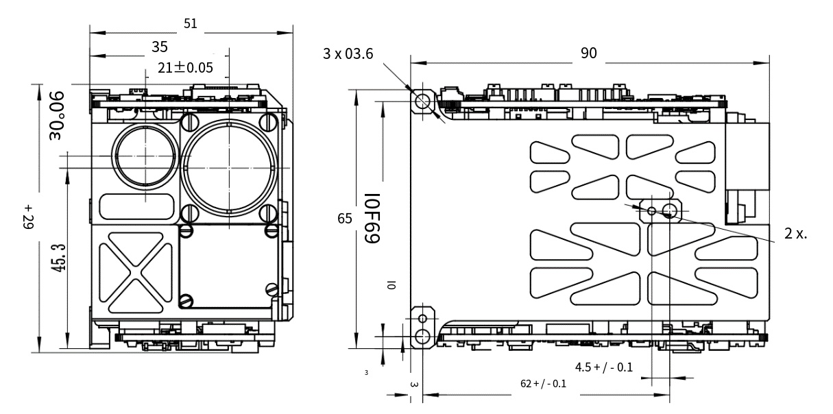
Figure 1 Interface diagram
COMMUNICATION PROTOCOL
4.1 Communication Protocol Definition
4.1.1 Asynchronous serial communication standard: RS422;
4.1.2 Baud rate: 115200bps;
4.1.3 Transmission format: 8 data bits, 1 start bit, 1 stop bit, no check bit;
4.1.4 For each byte of information, the lowest position (lsb) is transmitted first, and if it is a multi-byte message, the lowest byte is transmitted first.
4.2 The command sent by the upper computer system to the laser photometry module
4.2.1 Information header (0x55);
4.2.2 Command word 1;
4.2.3 Command word 2;
4.2.4 Command word 3;
4.2.5 The "message tail" is the checksum, the result of the xor operation of 1-4 bytes.
Table 1Command word 1 definition
| BIT07 | BIT06 | BIT05 | BIT04 | BIT03 | BIT02 | BIT01 | BUT00 |
|
0x00: Standby 0x01: Start self-test 0x02: Single ranging 0x03: Continuous Ranging (1Hz) 0x04: Continuous Ranging (5Hz) 0x05: Irradiation 0x08: Stop ranging/Irradiation 0x09: Gate setting 0xAA: Reports the cumulative number of laser pulses |
|||||||
Table 2 Command word 2 definition
| BIT07 | BIT06 | BIT05 | BIT04 | BIT03 | BIT02 | BIT01 | BUT00 |
|
When illuminated by laser: Laser code 1 to 8 When laser ranging: 1- first target 2- end target When the gating value is set: The distance gating value is low in bytes |
|||||||
Table 3 Command word 3 Define
| BIT07 | BIT06 | BIT05 | BIT04 | BIT03 | BIT02 | BIT01 | BUT00 |
|
Fast hair: Laser exposure time setting (1 ~ 47) When the gating value is set: the distance gating value is high in bytes |
|||||||
4.3 The laser photometer sends data to the system software
4.3.1 Information header (0x55);
4.3.2 Status word;
4.3.3 Target distance/cumulative number of laser pulses (2 bytes);
4.3.4 Current temperature of laser measuring module;
4.3.5 The "message tail" is the checksum, which is the xor operation result of 1-5 bytes.
4.3.1 Information header (0x55);
4.3.2 Status word;
4.3.3 Target distance/cumulative number of laser pulses (2 bytes);
4.3.4 Current temperature of laser measuring module;
4.3.5 The "message tail" is the checksum, which is the xor operation result of 1-5 bytes.
Table 4Information header description
| BIT07 | BIT06 | BIT05 | BIT04 | BIT03 | BIT02 | BIT01 | BUT00 |
|
0: No laser 1: Laser is present |
0: Ranging effective 1: Ranging invalid |
Laser mark 1/0 alternate |
1: Overtemperature alarm 0: The temperature is normal |
|
|
00: Standby 01: Ranging 02: Indication |
|
Target distance information Definition: The distance value is represented as an integer by 2 bytes (16BIT), which can be converted directly to decimal.
Cumulative laser pulse times definition: because the range of 16 bits of binary number is 0 ~ 65535, and the service life of the laser detector is one million times, so the agreed laser emission times for the multiple of the number of 20, the range is 0 ~ 1310700;
Laser measuring module current temperature: d7-d0: complement expression, value range -128℃ ~ +127℃.
ELECTRICAL INTERFAC
One RS422 interface, signal level in line with MAX488 chip characteristics. The interface definition is shown in Table 5:
Table 5 Interface definition
| Socket MOLEX 53048-0810 | ||
| Corresponding plug MOLEX 51021-0800 | ||
| Pin number | Signal name | Instructions |
| 1 | 24V | Power supply + |
| 2 | 24V | Power supply + |
| 3 | 24VGND | Power supply - |
| 4 | 24VGND | Power supply - |
| 5 | 422_A | Upper computer -> Laser photometry Assembly + |
| 6 | 422_B | Upper computer -> Laser photometric Assembly - |
| 7 | 422_Z | Laser photometry Assembly -> Upper computer - |
| 8 | 422_Y | Laser photometry Assembly -> Upper computer + |
| Socket MOLEX 530480210 | ||
| Corresponding plug MOLEX 151340201 | ||
| Pin number | Signal name | Instructions |
| 1 | SYNC_IN+ | The external sync_in signal is a differential signal with an interface type of RS422 |
| 2 | SYNC_IN- | |
ホットタグ: 25MJ 1064NMレーザーターゲット指定者、メーカー、サプライヤー、工場、中国、中国製、カスタマイズ、高品質
関連カテゴリー
905nm レーザー距離計モジュール
1535nm レーザーレンジファインダーモジュール
1570nm レーザーレンジファインダーモジュール
1.54umレーザーレンジファインダーモジュール
1064NMレーザーターゲット指定子
アンチドローンSTSTEMモジュール
測距ライダーモジュール
お問い合わせを送信
下記フォームよりお気軽にお問い合わせください。 24時間以内に返信いたします。


WIHT LRF")
WIHT LRF")